Centrifugal pumps account for the largest share of rotating equipment population at pipeline pump stations — typically 40 to 60 percent of all rotating assets at a mainline crude or products station. They also generate a disproportionate share of unplanned maintenance events, not because they are inherently unreliable, but because the failure modes are numerous, the onset is sometimes rapid, and the spectral signatures of different failure mechanisms overlap in ways that confuse simple threshold-based alarm systems. A cavitating pump and a pump with a developing bearing defect can produce similar overall vibration levels; the difference lies in the spectral content and the process variable correlations.
Cavitation: The Most Misdiagnosed Pump Failure Mode
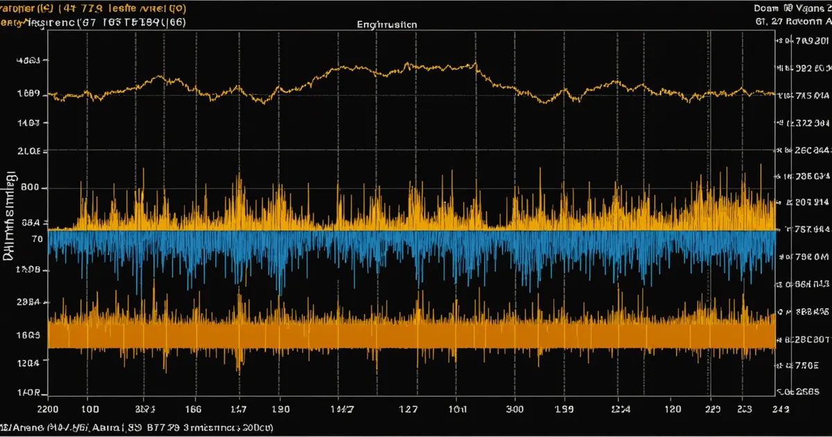
Cavitation occurs when local static pressure at the pump suction — specifically at the impeller eye — drops below the vapor pressure of the pumped fluid. Vapor bubbles form, travel into higher-pressure regions, and collapse violently. The acoustic signature is the familiar gravel-in-the-pump sound, but the vibration signature is less distinctive than many operators assume. Cavitation generates broadband high-frequency energy, predominantly above 10× running speed, along with elevated noise floor across the entire spectrum. On an accelerometer mounted on the bearing housing, cavitation may show up as elevated g RMS readings — perhaps 0.8–1.5 g RMS on a pump that normally runs at 0.3 g RMS — without producing the sharp spectral peaks that bearing defects or mechanical imbalance would create.
The diagnostic key for cavitation is process correlation: suction pressure and Net Positive Suction Head available (NPSHa) relative to the pump's required NPSH (NPSHr). If a pump starts showing elevated broadband vibration coinciding with a drop in suction header pressure — say, a seasonal drawdown in a pipeline receipt tank — cavitation is the first hypothesis to test, not bearing wear. A vibration system that logs process tags from the SCADA historian alongside vibration data makes this correlation straightforward; a system that logs vibration in isolation makes it a manual investigation.
On a five-pump mainline crude station in East Texas operating high-API gravity condensate, a reliability team documented a pattern where the two pumps on the lowest-level suction tie-in ran into cavitation during summer peak-demand periods when inlet pressure would drop to within 5 psi of NPSHr. The broadband vibration increase was significant enough to trigger velocity alerts on their ISO 20816 Zone B/C boundary, but the bearing defect frequencies were clean — no BPFI or BPFO energy, no subharmonics. Without the process pressure correlation, those alerts would have been investigated as bearing issues and the root cause (insufficient NPSH margin) would have been missed.
Rolling Element Bearing Wear: Reading Defect Frequencies
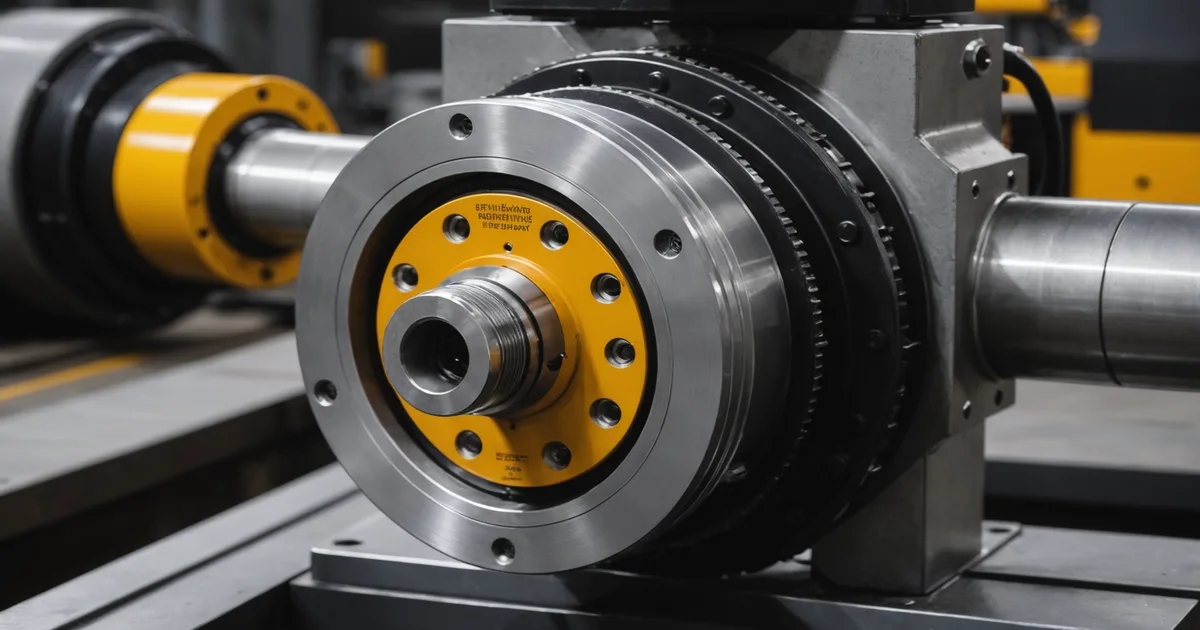
Most pipeline pump applications use rolling element bearings rather than the hydrodynamic (sleeve) journal bearings found in large centrifugal compressors. This is operationally significant because the vibration signature of rolling element bearing degradation is distinctly different from journal bearing wear, and the detection method depends on envelope demodulation of high-frequency acceleration signals rather than proximity probe displacement data.
Rolling element bearing defect frequencies are geometric functions of bearing geometry and shaft speed. For a bearing at 1800 RPM (30 Hz shaft speed), a typical inner race defect frequency (BPFI) might be in the range of 100–150 Hz, and an outer race defect frequency (BPFO) in the range of 80–120 Hz, depending on the bearing's ball count and contact angle. The fundamental train frequency (FTF, cage defect) is typically 0.4–0.5× running speed, or 12–15 Hz at 1800 RPM. Ball spin frequency (BSF) is typically 1.5–3.5× running speed.
Early-stage bearing defects are often detectable first in high-frequency acceleration (2–20 kHz range) before they generate energy at the defect frequencies in the 10–1000 Hz range. The standard diagnostic progression is: (1) elevated high-frequency energy (gSE, kurtosis > 3–4) indicating surface stress waves from defect impacts; (2) sidebands appearing around defect frequencies; (3) growing harmonic families (1× BPFI, 2× BPFI, 3× BPFI) as the defect propagates; (4) rise in overall velocity/acceleration as damage becomes severe. A condition monitoring system that captures only low-frequency vibration from an SCADA historian at 1-second scan intervals will miss stages (1) and (2) entirely. Stage (3) may be visible in the spectral data if the historian is configured to capture spectral bands, not just overall RMS values.
Mechanical Seal Failure: Process Variables Tell the Story
Mechanical seal degradation in centrifugal pumps is arguably the failure mode least suited to vibration-based detection and most suited to process variable monitoring. A failing seal face produces increasing leakage — detectable as rising seal flush pressure differential, increasing seal pot temperature, or (for dual mechanical seals) rising barrier fluid pressure fluctuation. By the time a failing seal has degraded enough to produce detectable vibration changes, the seal is typically close to catastrophic failure.
That said, there are indirect vibration signatures associated with seal degradation. A seal running dry (due to barrier fluid loss) generates friction heat that can cause the shaft to bow, leading to 1× vibration at running speed — which looks identical to mechanical imbalance or soft foot. Running-dry seal failure also tends to occur rapidly, often progressing from detectable to catastrophic in hours rather than days. The monitoring implication is that seal condition monitoring should be primarily process-variable-based: monitor seal pot temperature, barrier fluid level/pressure, and seal flush flow as the leading indicators, and treat unexpected 1× vibration increases on seal-critical assets as a confirmation signal rather than a standalone primary alert.
We are not saying vibration monitoring is irrelevant to seal health — it is relevant as a secondary indicator. We are saying that over-relying on vibration data for seal failure detection, while ignoring the process variable indicators, is a diagnostic architecture mistake that leads to missed early warnings.
Impeller Wear and Hydraulic Imbalance
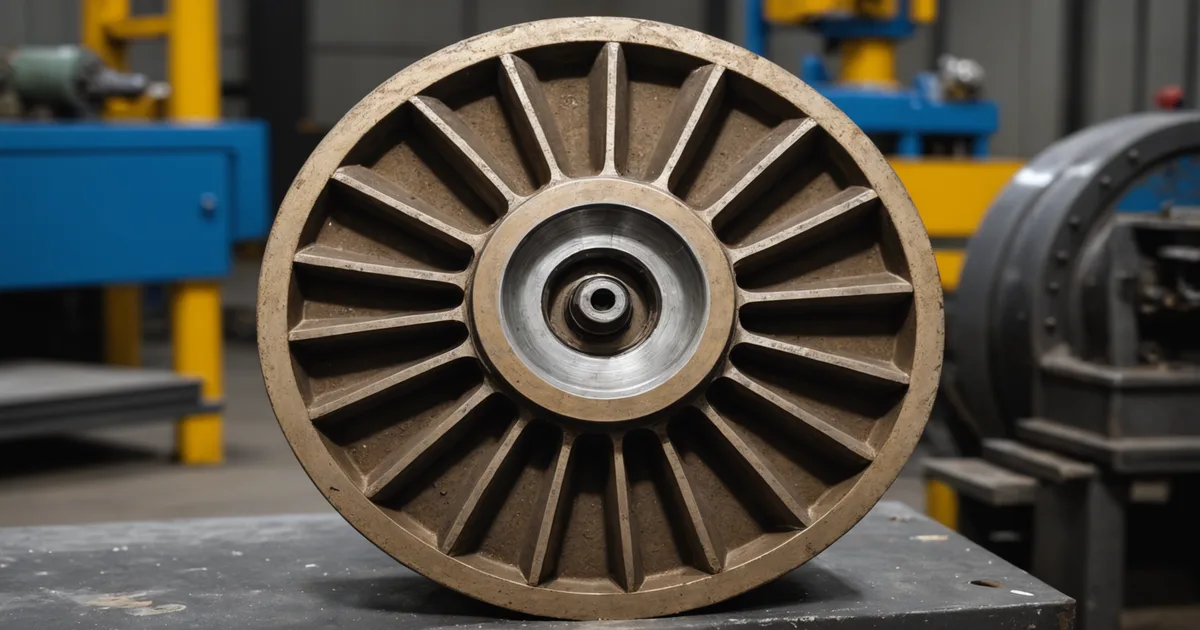
Wear ring clearance erosion and impeller damage (from abrasive particles, cavitation damage, or corrosion) change the hydraulic balance of the rotor. As wear ring clearances increase, the differential pressure force on the impeller decreases, leading to reduced axial thrust compensation and increased thrust bearing loading. Vibration in this mode often presents as elevated 1× (running speed) amplitude, sometimes with a 2× component, and may show increasing axial vibration relative to radial — a pattern consistent with changes in axial loading.
For API 610 pump designs, wear ring clearances are specified in the standard, with minimum acceptable clearances that increase with shaft size. Radial clearances typically start in the range of 0.3–0.5 mm for smaller pumps and can double or triple before hydraulic performance degrades enough to be noticeable on process variables. Long before process performance degradation is evident, the vibration signature may show the early signs of hydraulic imbalance — and that is the window for condition-based ring clearance assessment and repair scheduling.
Building a Multi-Variable Diagnostic Picture
The recurring theme across all three failure modes — cavitation, bearing wear, and seal degradation — is that single-variable vibration monitoring, while necessary, is insufficient for reliable early detection. The most actionable diagnostic picture comes from correlating vibration data (overall velocity/acceleration, spectral bands, kurtosis trend) with process data (suction pressure, differential pressure, flow rate, bearing temperature, seal condition indicators) over time.
This is exactly the architecture that SCADA historian integration enables. An AVEVA PI historian or equivalent already has most of these process tags being logged from the DCS at a pump station; adding vibration data to the same time-series store — whether from Emerson AMS, Bently Nevada, or direct accelerometer transmitters — creates the multi-variable dataset needed for reliable failure mode discrimination.
The practical goal for a pipeline pump station is to go from reactive (the pump has failed) to predictive (this pump shows developing bearing defect frequency growth trending at a rate suggesting action needed within 3–6 weeks). Achieving that requires not just the sensor data, but the analytical layer to extract defect frequency band energy from raw spectrum data, correlate it with operating condition covariates, and track the trend trajectory rather than just the instantaneous level.
We built Midstreamly's failure mode library specifically around midstream centrifugal pump populations. Book a technical session to see how your equipment types are covered.